❑The PCIe-IIRO 8 Channel Relay Card may be used to either open or close a relay based on the Criteria established in the SPA
•As an example, you can do one based on the Alarm Condition. As an example, if the Central Station Receives a Fire - which is the condition F - then the relay will open or close.
•Then at the Subscriber's side, they can put a power light to flash, and/or a Sounder; or trip a Contact to an alarm panel, etc.
Relay Board Software and Hardware Installation
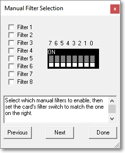
1. Do not install card into the computer until the software has been fully installed, but verify these settings before continuing.
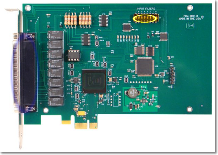
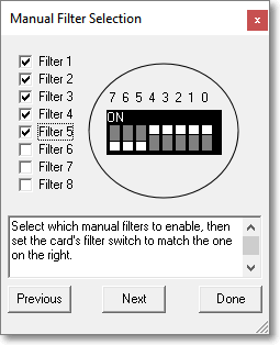
* All dip switches must point down toward motherboard in PC (off position) This should be the default setting when you receive the card. If the dip switches are all pointing toward the top of the board they are in the wrong position, please verify before continuing.
2. Software Installation
Download the software PCIe-IIRO-8 Software Package
Direct link http://accesio.com/files/packages/PCIe-IIRO-8%20Install.exe
File Name PCIe-IIRO-8 Install.exe
Available Reference Manuals - optional
PCIe-IIRO-8 Manual (.PDF)
Direct link http://accesio.com/MANUALS/PCIe-IIRO-8.pdf
Available Datasheets - optional
PCIe-IIRO-8 Data Sheet (.PDF)
Direct link http://accesio.com/MANUALS/PCIe-IIRO-8%20Datasheet.pdf
It’s recommended that you be logged into the machine with full administrative permissions. Not a user who has been given administrative rights, use the PC Administrative account.
{if the machine is running Win7 or Windows 8 remember to run as administrator}
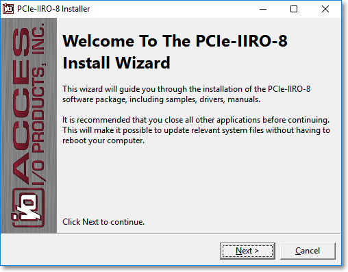
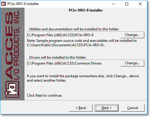
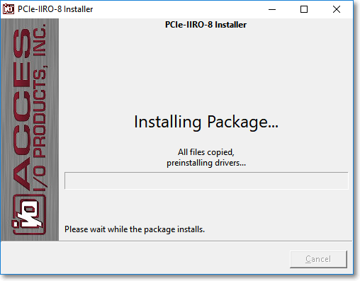
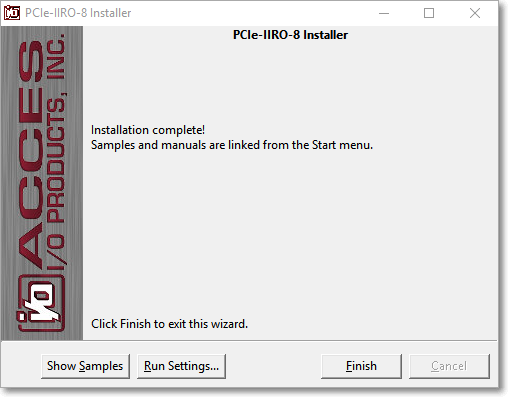
Run the PCIeIIRO-8 Installer executable and accept all the default selections, you’ll click NEXT twice, and then click Install. You will get three Windows Security Pop up messages asking you to confirm Installation.
3. Turn OFF computer power AND unplug AC power from the system. Hold the PC power button in for a few seconds to dissipate any remaining power. This is an electronic circuit board; please make all attempts to reduce your static potential before touching this card or putting it into the computer. If you are not familiar with how to do this there are many articles on the internet regarding electrostatic discharge.
Here is one good link for review - https://www.computerhope.com/esd.htm
❖ Failure to do so could damage the board and your computer.
4. Remove the computer cover.
5. Carefully install the card in an available PCIe expansion slot (you may need to remove a backplate first).
6. Inspect for proper fit of the card and tighten screws. Make sure that the card mounting bracket is properly screwed into place and that there is a positive chassis ground.
7. Once the card is in place inside the computer, connect one end of the ribbon cable to the connector on the PCI-IIRO-8 and then connect the other end to the STB-37 terminal board. Secure the screws on both ends of the cable prior to production, use, and testing.
8. Replace the computer cover and turn ON the computer which should auto-detect the card (depending on the operating system) and automatically finish installing the drivers.
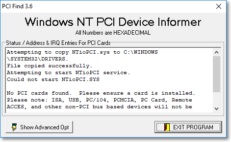
9. Run PCIfind.exe to complete installing the card into the registry (for Windows only) and to determine the assigned resources. (‘Assign Resources to Relay Board’)
10. Run one of the provided sample programs that was copied to the newly created card directory to test and validate your installation. (optional step)
❑Assign Resources to Relay Board
From the Windows Start Menu / All Programs / Access PCIe-llRO-8 /
Select the application labeled AIOWDMFind
(NOTE: the install may put a PCIFind.exe on the desktop, this is not the same application and this icon may be removed)
If the card is inserted properly in the PC you should see a similar window as below:
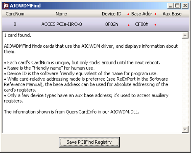
** copy the Base Addr to notepad as you will need this address in the next step – ‘Change the HEX address to Decimal for use in the Signal Processing Application’
(the Base Addr is highlighted in the example above with RED DOTS – CF00 – the small h indicates HEX and you will not use this letter as part of the address)
Select Save PCIFind Registry – you should get a ‘Success’ window, you may close these applications now.
❑Change the HEX address to Decimal for use in the Signal Processing Application
Now we just need to convert the Hexadecimal Base Address to a Decimal Value, then we can use that decimal value to program Signal Processing Application to use the relays on the relay board. We will use the Calc *Calculator’ application to perform this last step.
Start your Calculator application. Depending on the version of windows, you should either click Start, then Calculator, or Start / Run / Calculator. The document was created using Windows 10 Calculator – which is much easier to use than prior versions. We’ll try and include the appropriate actions for versions prior to Windows 10.
When the Calculator application opens it normally opens in Standard Mode.
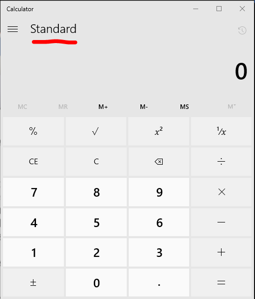
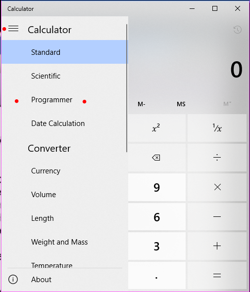
To convert a hexadecimal number to a decimal number you need to change the Calc app to ‘Programmer’ mode. Click the ellipse (three lines stacked button) to the left of the word ‘Standard’ and select ‘Programmer’ – example below
Select the HEX key (use the mouse and click the word HEX on the left-hand side of the app, once you click HEX you will see the blue line indicator off to the left of the word HEX) now enter Base Addr of the I/O board (which in our example is CF00) into the calculator and you will see the decimal value appear below the HEX Value. 52992
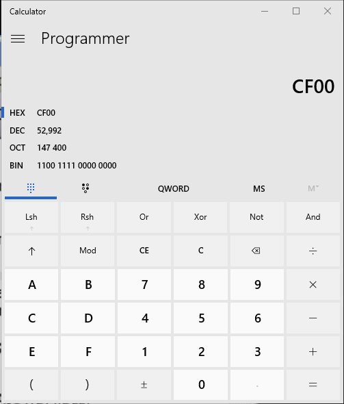
(in older versions of Calculator, you must then press the DEC key and it will change your hexadecimal value to a decimal value, it doesn’t automatically display the value as it does in Windows 10 Calculator)
Now we have the decimal number to program the Signal Processing application, we just need to open Signal Processing application and enter the information in the Relay Card Tab.
Bring Spa up on the desktop
Select Setup
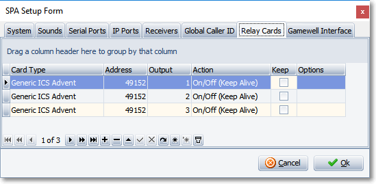
Select the ‘Relay Card’ Tab
To insert a new record, press the <Ctrl><Insert> keys at the same time, or click the plus sign. You only need to create a new record for every relay that you want to use. If you only need to use one relay it is not necessary to create all 8 entries as shown in our example.
Card Type - Select the only option for Card Type as Generic ICS Advent
Address - Enter the Decimal Address number you converted from HEX in the ADDRESS field (Type the Decimal number not the HEX - Example 52992)
Output - Enter the Output relay number that you wish to activate, since this board has eight relays, you can enter any value between the numbers 1 to the number 8.
Action - *** Most Important Step *** This is where you can tell the software when each relay is supposed to close the loop. It’s recommended that you test your relays, so initially we would suggest you select the option to On/Off {Keep Alive}. Once you have completed your testing you will have to come back to this option and set it to how you want that relay to behave. See ‘Select Actions’ for more information.
Keep – by default this option box is not selected. If checked, the relay that is forced closed will stay closed until someone physically goes into Spa, Selects Relay Card from the system menu and forces the relay to open by selecting the active relay from the list and clicking on it.
Make sure you save the changes you make by clicking the check mark. Repeat this process for each relay that you want to use in the Signal Processing Application just remember that the Output number should be different for each entry. (1 – 8). A full restart of Spa will be required, Stop, Exit, then restart Spa.
You may now move forward to the section below titled ‘Testing your Relay Board with a Multimeter’
Signal Processing Program Example
❑Testing your Relay Board with a Multimeter
The easiest way to test to see if your Relay Board is working properly is with a multi-meter. You can pick them up almost anywhere and if you’re not sure just Google ‘buy multimeter’ and you will be presented with a half a dozen meters or more. You don’t need an expensive one to do this test. Unfortunately, teaching you how to use the multi meter is beyond the scope of this document but we feel that you will have enough information to succeed!

Select the OHM’s option (looks like this - Ω) on the Multimeter. Some meters will make a sound when the two connectors are touched together indicating a short. Others may just return results in the digital read out that should be close to zero indicating a short or no resistance.
You can use either Micro Key’s Signal Processing Application to test your board, or you can use a Software package that installed from the vendor. Either will suffice to verify that the relays are working. Obviously using Signal Processing Application will verify that the board is working with our application. If you are only using 1 relay it may be easier to just test it using our application. But if you are going to be testing multiple relays it might be easier to use the vendor’s application. In this document, I will cover both methods.
❑Using Signal Processing to test the Relay Card
If you are going to be using one relay it may be easier to just use the Signal Processing Application to test your relay. To do so, just make sure the Action field on the relay tab for your relay is selected as On/Off {Keep Alive}. This option is used for testing as it forces the Signal Processing Application to close the loop for 10 seconds, then open the loop for 10 seconds repeatedly. Start Spa by clicking Start. When Spa is started the icon below the word start will be green and the label for the button will change to Stop. If you have done everything correctly, you should start hearing the relays close and open every 10 seconds.
Now you just need to know what pins to check to verify that the relay is working and this will depend upon what relay you programmed into the software. Review the following table for that information.
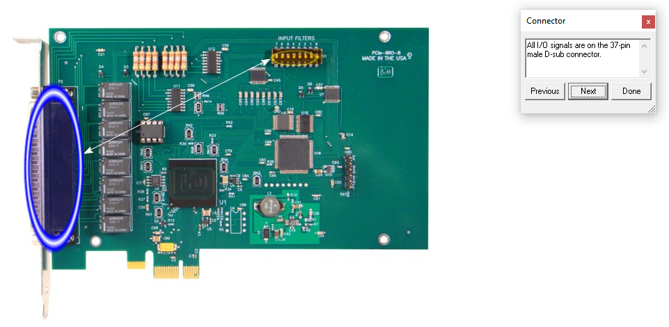
Connector Pin Assignments Table for the STB-37 Terminal Board
Test Pin Test Pin
↓ ↓
Relay Output # |
Pin (Normally Open State) |
Common
|
Pin |
1 |
19 |
37 |
18 |
2 |
36 |
17 |
35 |
3 |
16 |
34 |
15 |
4 |
33 |
14 |
32 |
5 |
13 |
31 |
12 |
6 |
30 |
11 |
|
7 |
29 |
10 |
|
8 |
28 |
9 |
|
So, if you want to test Relay Output 1, place one of your multi meter leads on Pin 19 and the other on pin 37 of the terminal board. As the relay is closed the multi meter should either make a sound for 10 seconds or the digital value in the read out should go to zero. When the relay is opened the sound on the meter should either stop or the number in the digital read out should increase to a higher number than 0 indicating an OPEN or infinite resistance. For Normally Open, connect your device to the relay and pins, Normally Open and Common. This means the relay must activate to close the circuit completing a circuit for whatever device is wired.
Once you have verified that the relay is working properly you’ll need to go back into Signal Processing setup and set the Action for that relay to your desired action. See ‘Select Actions’ for more information.
Relay’s 1 – 5 support the opposite wiring if you need a relay that is begins in a closed state and when activated the circuit is then opened. You would wire for relay 1, pins 37 and 18. Relay’s 6 – 8 only support the Normally Open state.
Using the Vendor’s application to test the Relay Card
If you are using multiple relays on the relay card you may find it easier to use an application that is installed at the time you install the drivers for the card. You should be able to locate it by clicking on
Start button - then
All Programs - then
ACCES PCIe-IIRO-8 – the exact info for the XXX may be different depending upon the card installed) - then
Delphi – then
Iiro8.exe
This will launch an application that looks like this:
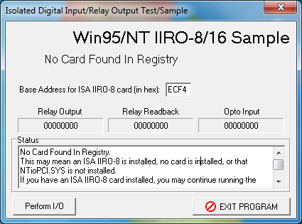
Enter in the HEX the value for the Base DIO that you wrote down earlier. This is entered into the field labeled Base Address for ISA IIRO-9 card (in hex). The difference between this application and Spa is that this application closes and opens each relay one after another continuously. To start it, click Perform I/O and the program will start at the right zero in the Relay Output field which represents Output 1 in our software. You can still use the same Connector Pin Assignment table to monitor the appropriate pins.
Once you have verified that the relays are working properly you may need to go back into Signal Processing setup and verify that the Action for that relay is selected to your desired action.
See ‘Select Actions’ below for more information.
❑Select Actions – for Signal Processing
There are 16 possible options that you can set for a relay in the Signal Processing Application and this section will explain what each of these options mean.
On Operator Alert
Selecting this option will change the state on a selected relay any time a signal is presented to an operator. When a signal is presented to an operator the status of that signal is ‘A’ for alerting, and that’s what is meant by On Operator Alert.
On Spa System Error
Selecting this option will force the Signal Processing Application to change the state of the relay on a SPA System Error.
Pending Signals Exceed 1,5,10,15,20,25
Selecting any option with this label will cause the Signal Processing Application to change the state on a relay when the count of Pending Signals exceeds the number indicated in the selection. This again refers to the status of signals in the Alarm Stack. Status = P (Pending)
On Operator Alert Over 1,3,5,10,15 Minutes
Selecting any option with this label will cause the Signal Processing Application to monitor how long an Alarm stays in the alerting Status = A (Alerting) and if that time exceeds the number selected the application will then change the state on the selected relay.
On / Off {Keep Alive}
Selecting this option will force the Signal Processing Application to repeatedly change the state on the relay for 10 seconds and then change it back. This is used mostly for testing purposes.
Unattended Alarm
Select this option to force the Signal Processing Application to change the state on the relay when there is an Unattended Alarm activation.
On Alarm Condition
Selecting this option will force the Signal Processing Application change the relay state when a specific alarm is received, if that alarm is assigned any defined alarm condition that you program under Options. For example, if you want some device to turn on when a fire alarm or burglary alarm is received you would just need to know the alarm condition codes for Fire and Burglary, and then enter those conditions in the Options field. Click on the Options field and type in the Alarm Conditions that you want. Separate multiple conditions by a space and then a comma. This function does NOT work with manually generated signals.
If you the relay state to change when a Fire Alarm, Burglary Alarm and Hold Up Alarm is received then click on the last column field labeled Options, and then enter F , BA, HU and save it
Example: F , BA , HU spaceFspace,spaceBAspace,spaceHU
Your alarm conditions list can be found in the data entry application (MKMS.exe) under Maintenance, General Maintenance, and Alarm Conditions.
Lastly, anytime you make a change to the Relay Board Tab, this will require a restart on the Signal Processing Application (i.e. Stop, Exit, re-Launch SPA.exe)
04/28/2018